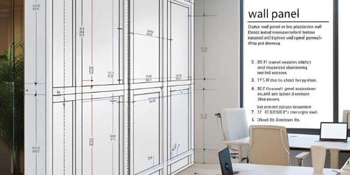
Wall panel shop drawings are an essential component of architectural and construction projects, They providesd precise details for fabricating and assembling wall panels. These drawings serve as a communication tool between architects, engineers, fabricators, and installers, ensuring that every element is correctly manufactured and installed according to design specifications.
To maintain clarity and accuracy, wall panel shop drawings use a standardized set of symbols, abbreviations, and notations. These elements help convey critical information, such as material specifications, panel dimensions, connection details, fastener types, and finishing instructions. Understanding these symbols is crucial for anyone working with wall panel drawings, from drafters and project managers to contractors and on-site installers.
In this article, we will explore the key symbols and notations commonly found in wall panel shop drawings. We will break down their meanings, explain their significance, and provide practical examples of how they are used in real-world projects.
Understanding Wall Panel Shop Drawings
Wall panel shop drawings are detailed technical drawings that show how wall panels will be manufactured, assembled, and installed. These drawings act as a guide for fabricators, contractors, and architects to ensure accuracy in construction.
A wall panel shop drawing includes dimensions, materials, finishes, and connection details. It also shows how different panels fit together, helping avoid mistakes during installation. These drawings are especially useful for prefabricated wall panels, which are built off-site and later installed on the building.
Accuracy in shop drawings is important because any errors can lead to delays and extra costs. That’s why drafters use software like AutoCAD or Revit to create precise drawings. The shop drawing process also involves reviewing architectural and structural plans to ensure everything matches the project requirements.
For contractors, these drawings provide a step-by-step assembly guide, reducing confusion on-site. They also help clients and architects visualize the outcome before fabrication begins.
Common Symbols Used in Wall Panel Shop Drawings
Wall panel shop drawings use different symbols to represent materials, components, fasteners, edges, and finishes. Understanding these symbols is important for accurate fabrication and installation.
Material and Component Symbols
These symbols indicate the type of materials used, such as plywood, MDF, or solid wood. They also show different components like panels, backers, and reinforcements. Each material has a unique symbol, making it easy to identify in the drawing.
Fasteners and Connection Symbols
Fasteners like screws, nails, bolts, and dowels have their own symbols. These symbols show how the panels are attached and where reinforcements are needed. Properly reading these symbols helps ensure strong and secure connections.
Edge and Joint Symbols
Edge treatments and joints are crucial in wall panel installation. Symbols for joints indicate whether the panels will be butt-jointed, mitered, or tongue-and-groove. Edge symbols define finishing details, such as veneer edge banding or solid wood lipping.
Finishing Symbols
Finishes protect the panels and enhance their appearance. Symbols for finishing indicate whether a panel will be painted, laminated, or stained. These details ensure that the final product meets design and durability requirements.
By understanding these symbols, drafters, fabricators, and installers can work more efficiently, reducing errors and miscommunication. Accurate shop drawings lead to better-quality wall panels and a smoother construction process.
Key Notations in Wall Panel Shop Drawings
Wall panel shop drawings use specific notations to ensure accurate manufacturing and installation. Understanding these notations is essential for architects, engineers, and fabricators.
Dimensioning and Measurement Notations
These notations indicate the size, height, width, and depth of the wall panels. They include overall dimensions and specific measurements for cutouts, joints, and edge details. Precise dimensioning ensures that the panels fit correctly in the construction.
Section and Detail Notations
Section notations show cross-sectional views of the wall panels, helping to visualize internal layers, materials, and connections. Detail notations provide zoomed-in views of specific areas, such as fasteners, joints, and finishes. These notations help fabricators understand how different parts come together.
Panel Orientation and Placement Notations
Orientation notations indicate how a panel should be positioned—vertically or horizontally. Placement notations specify the exact location of each panel in the overall structure. This ensures proper alignment and avoids installation errors.
Load and Structural Notations
These notations highlight the load-bearing capacity of the panels, wind resistance, and other structural requirements. They also specify reinforcement details, such as steel inserts or anchoring points. This information is critical for ensuring safety and durability.
By understanding these key notations in wall panel shop drawings, construction teams can improve accuracy, minimize errors, and ensure smooth installation. These details help maintain structural integrity and efficiency in building projects.
Reading and Interpreting Wall Panel Shop Drawings
Wall panel shop drawings are detailed plans that show how wall panels are built and installed. These drawings help architects, engineers, contractors, and manufacturers ensure that the panels fit correctly and meet project requirements.
Key Elements of Wall Panel Shop Drawings
- Dimensions – The drawings provide exact measurements of the panels, including height, width, and thickness.
- Materials – They specify the type of materials used, such as wood, metal, or composite panels.
- Connections – Details about how the panels will be attached to the structure are included.
- Finishes – The drawings indicate surface treatments like paint, veneer, or laminates.
- Section Views – Cross-section views show how different parts of the panel fit together.
How to Interpret the Drawings
- Start with the Title Block – This section contains important information, such as project name, drawing number, and scale.
- Check the Legends and Symbols – These help you understand the notations used in the drawing.
- Follow the Dimensions – Compare them with the site measurements to ensure accuracy.
- Look at the Assembly Details – These show how each panel connects to other parts of the structure.
Conclusion
Wall panel shop drawings are an essential part of construction and fabrication, providing detailed instructions for manufacturing, assembling, and installing wall panels. By using standardized symbols and notations, these drawings ensure clarity and precision, minimizing errors and streamlining communication among architects, engineers, fabricators, and installers.
Understanding key symbols—such as those for materials, fasteners, edges, and finishes—enables professionals to interpret the drawings accurately. Likewise, recognizing crucial notations related to dimensions, sections, panel orientation, and structural requirements ensures that the panels fit perfectly and perform as intended.
A thorough knowledge of these shop drawings helps improve efficiency, reduce costly mistakes, and maintain structural integrity in building projects. Whether you're a drafter, contractor, or manufacturer, mastering the interpretation of wall panel shop drawings is vital for achieving high-quality results in construction.